Overview
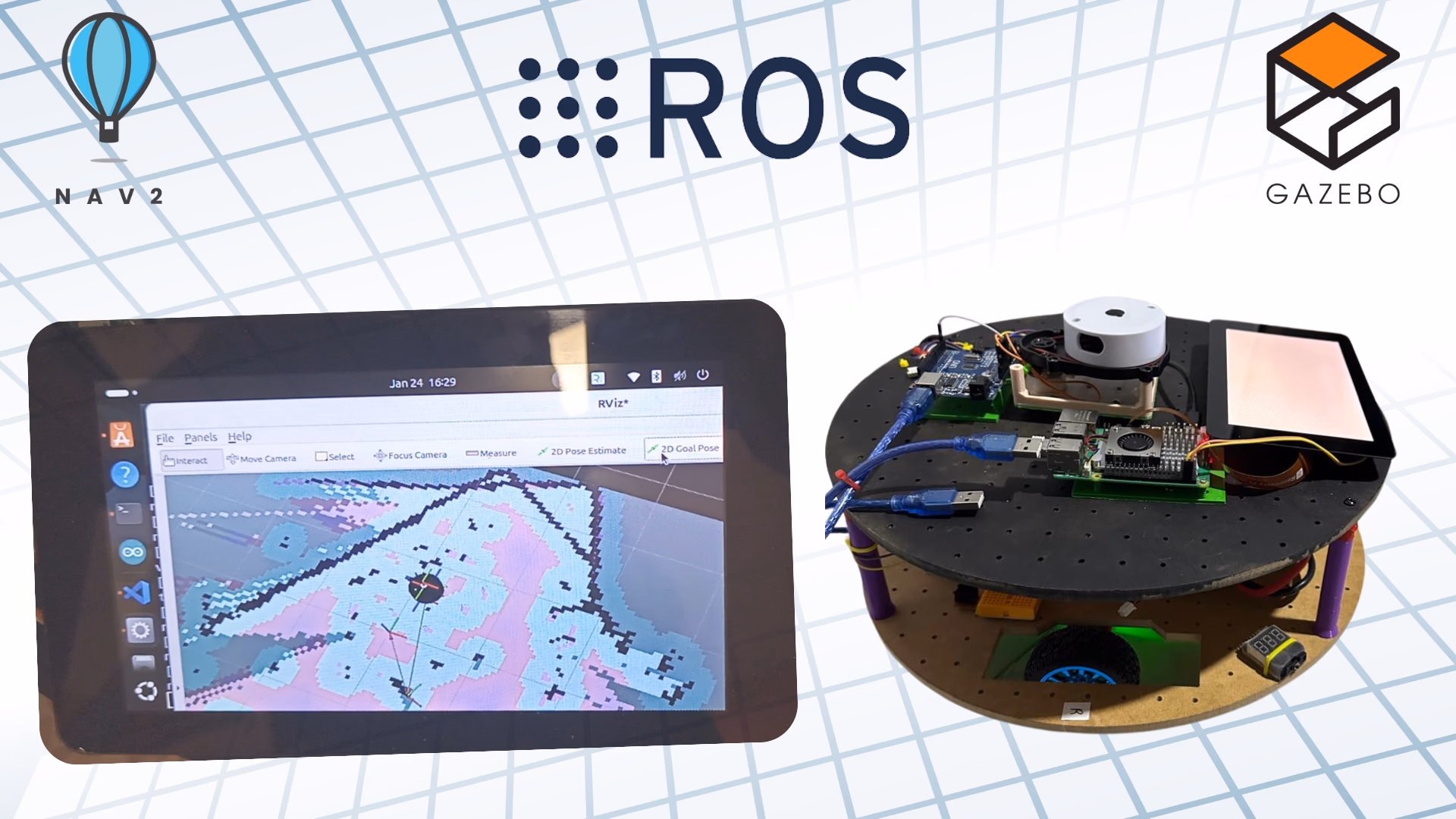
This project delivers an end-to-end autonomous navigation system for a differential-drive mobile robot, designed around the ROS 2 ecosystem. We start from the physical model (URDF + Blender), move through sensor integration (LiDAR + rotary encoders), set up the simulation (Gazebo + RViz2), and culminate in Grid-Based FastSLAM, AMCL localization, and the Nav2 stack for static and dynamic obstacle avoidance — all validated in simulation and on a real robot.
“A complete autonomous navigation stack: perceive, map, localize, plan, and act — coherently, in ROS 2.”
Problem Statement
Reliable autonomous navigation for differential-drive robots requires precise localization, accurate mapping, and robust path planning — and existing approaches often integrate these components poorly. The result is brittle behavior: drift, collisions, replanning loops, and failure in dynamic environments.
This work bridges that gap by integrating Grid-Based FastSLAM with AMCL inside ROS 2, anchored on a clean URDF-based robot model and validated in both Gazebo and the real world.
Objectives
- Design a URDF-based differential-drive robot with realistic kinematics and sensors.
- Generate accurate occupancy maps using Grid-Based FastSLAM.
- Maintain a globally consistent pose with AMCL correcting odometry drift.
- Plan and execute trajectories using Nav2 with reactive obstacle avoidance.
- Validate the stack in Gazebo simulation and on a physical robot.
System Architecture
The full stack is layered as follows — perception feeds mapping, mapping feeds localization, localization feeds the planner, the planner feeds the controller, and the controller drives the robot.
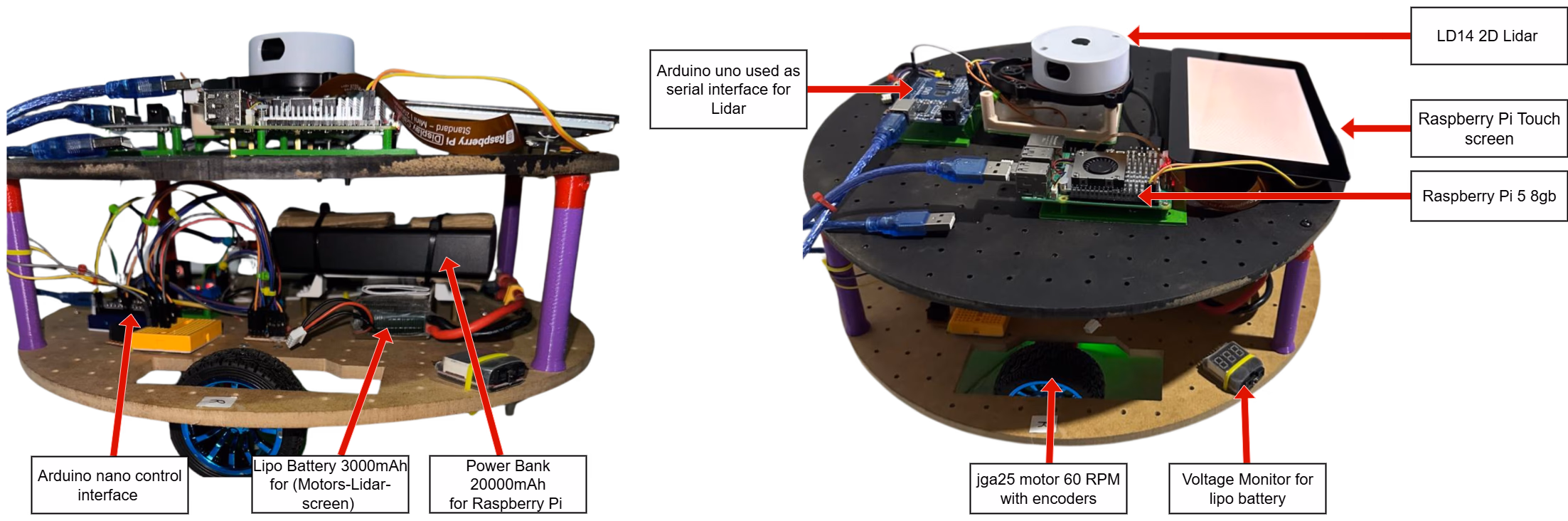
Differential-Drive Robot Design
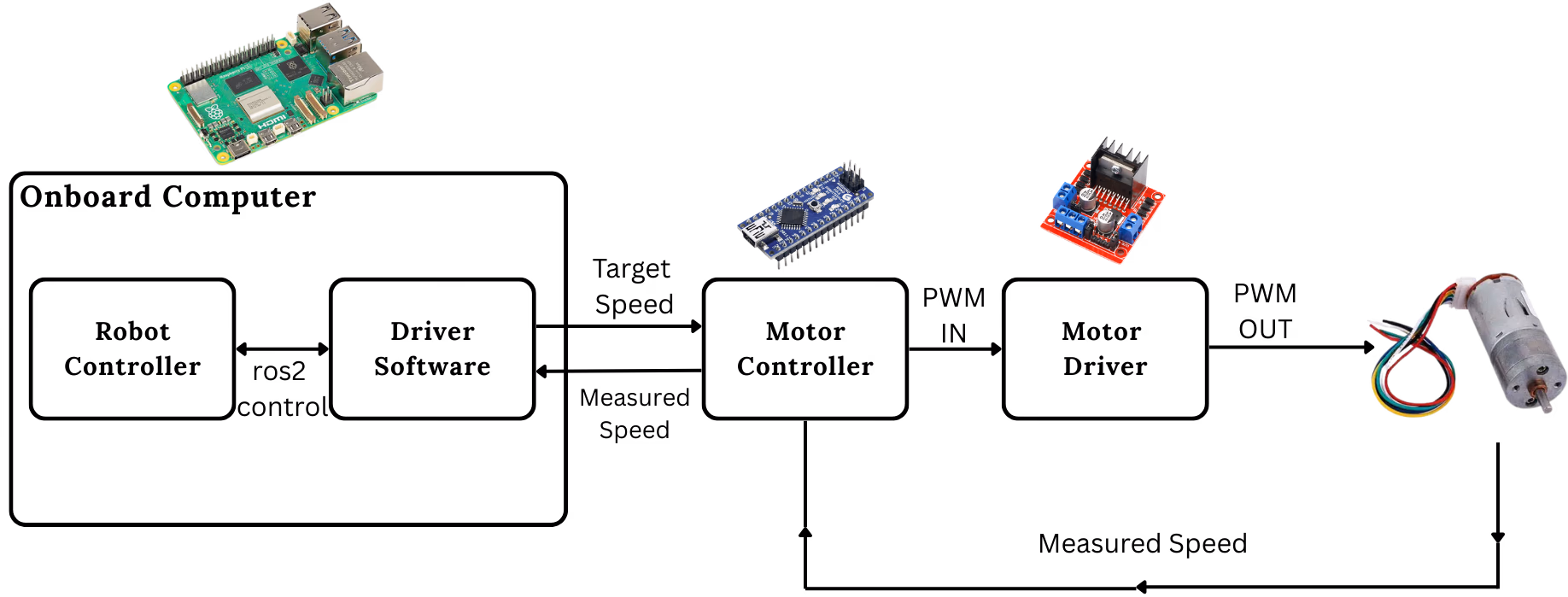
The platform is a small cylinder-shaped chassis carrying two driven wheels in the middle and two caster wheels (front + back) for stability. The compute stack is a Raspberry Pi 5B (high-level) talking to an Arduino Nano (motor control), with a 2D LiDAR for perception and rotary encoders for odometry.
Kinematic model
The robot’s translation and rotation are governed by the standard differential-drive kinematics:
v = (vR + vL) / 2
ω = (vR − vL) / d
Forward odometry is integrated from encoder ticks:
Δx = (r/2) · (Δenc_R + Δenc_L)
Δθ = (r/d) · (Δenc_R − Δenc_L)
where r is the wheel radius and d is the track width.
URDF & TF tree
The robot is described modularly in URDF — chassis, wheels, sensors, and joint types are split into includes for maintainability. ROS 2’s robot_state_publisher then broadcasts the full world → odom → base_link → laser/wheel_link transform chain, following REP-105 conventions.
Sensor Integration
| Sensor | Role | ROS 2 Topic |
|---|---|---|
| 2D LiDAR | Range-bearing scans for SLAM and obstacle avoidance | /scan |
| Rotary encoders (×2) | Wheel ticks → odometry pose | /odom |
cmd_vel actuation | Linear & angular velocity commands | /cmd_vel |
LiDAR is the primary perception sensor — its distance + intensity returns drive both map construction and AMCL’s measurement update. Encoders provide the motion model prior, but they suffer from drift on uneven floors — which is exactly what AMCL is there to correct.
Gazebo Simulation & RViz2
Validation begins in Gazebo with a custom world (obstaclesworld) full of walls and obstacles. The libgazebo_ros_diff_drive plugin maps /cmd_vel to wheel velocities, publishes /odom, and broadcasts the TF chain — a near-perfect proxy for the real robot.
RViz2 is the visualization layer: live LiDAR cloud, the growing occupancy grid, AMCL particle cloud, the global plan, the local trajectory rollouts, and the robot footprint — all on one canvas.
Grid-Based FastSLAM
We use Grid-Based FastSLAM because it gives us:
- Memory efficiency — the world is discretized into a grid of occupancy cells.
- Robustness — particle filters handle non-linear motion and noisy observations gracefully.
- Loop-closure friendliness — important for indoor environments with corridors and rooms.
The algorithm alternates prediction (motion model) and correction (sensor model) for each particle:
for each particle k:
    x_t[k]  = MotionUpdate(u_t, x_{t-1}[k])
    w_t[k]  = SensorUpdate(z_t, x_t[k])
    m_t[k]  = UpdateOccupancyGrid(z_t, x_t[k], m_{t-1}[k])

resample particles ∝ w_t
Tuning happened in mapper_params_online_asynchronous.yaml — sensor-fusion gains, dynamic-object handling, map adaptation rate, and resampling thresholds were all tuned for our LiDAR/encoder pair and our indoor environment.
AMCL — Adaptive Monte Carlo Localization
Once a map exists, AMCL keeps the robot’s pose locked to it. A particle filter spreads hypotheses across plausible poses and resamples them based on how well incoming LiDAR scans match the map. The loop is:
The closed loop base_link → odom → map is what saves us from cumulative odometry error: each AMCL update silently corrects the map → odom offset, so the robot’s map-frame pose stays consistent over arbitrarily long runs.
Nav2 — Planning & Obstacle Avoidance
The Nav2 stack sits on top of the map + AMCL pose and turns goals into motion. It splits the work into:
- Global Planner (Dijkstra / A*) — computes a long-horizon path on the static costmap.
- Local Controller (DWB) — refines that path in real time using the live LiDAR and the local costmap.
- Recovery Behaviors — clear costmaps, spin in place, back up — automatic resilience when the robot gets stuck.
Static obstacles come from the SLAM map; dynamic ones (people, moving boxes) come straight from live LiDAR — both fuse into a single costmap that the local planner re-evaluates at every control tick.
Tooling & Stack
- ROS 2 Humble (with
ros2_controlfor hardware interfaces) - SLAM Toolbox — async online mapping
- Nav2 — full navigation stack (planners, controllers, behavior trees, recoveries)
- AMCL — particle-filter localization
- Gazebo — physics + sensor simulation
- RViz2 — visualization
- Blender — 3D mesh design for the URDF
- Python / C++ — node implementations
- Raspberry Pi 5B + Arduino Nano — the on-robot compute
Real-World Deployment
After validation in Gazebo, the same stack was deployed on the physical robot. The key real-world adjustments:
- Encoder calibration — measured wheel circumference and track width were tuned until simulated and physical odometry agreed within ~2% over a 5 m straight test.
- AMCL covariance tuning — bumping
alpha1..alpha5reflected real wheel slip on tile floors. - LiDAR mounting offset — the laser frame transform was measured precisely from the URDF model so map alignment stayed clean.
The result: the robot consistently completes navigation goals in real indoor environments, smoothly avoiding both furniture (static) and people walking through (dynamic).
Watch the Robot
Future Work
- Multi-robot SLAM with map-merging across a fleet
- Visual-LiDAR fusion for richer feature association in low-feature corridors
- Semantic mapping — labeling rooms / doors / objects on top of the geometric map
- 3D Nav2 for stair-climbing or uneven terrain platforms
Contributors
- Imad-Eddine NACIRI
- Oussama Errouji
- Jade Bousliman
Supervisor: Pr. Mostafa Mrabti — National School of Applied Sciences, Fez, Morocco.
Takeaway
Autonomous navigation isn’t one algorithm — it’s a contract between perception, mapping, localization, and control. ROS 2 + SLAM Toolbox + AMCL + Nav2 is a stack that respects that contract, and this project shows what it takes to make it work end-to-end, from URDF to real-world deployment.